¶ title: openGL介绍
author: 李何佳
sidebar_label:openGL介绍
¶ 1. 概况
¶ 目的
本文档介绍在 QML 中如何使用 openGL,以及 C++中调用 openGL。
¶ 使用范围
适用于 SyberOS5.3 版本。
¶ 2. 着色器效果(Shader Effect)
着色器允许我们利用 SceneGraph 的接口直接调用在强大的 GPU 上运行的 openGL 来创建渲染效果。着色器使用 ShaderEffect 与 ShaderEffectSource 元素来实现。着色器本身的算法使用 openGL Shading Language(OpenGL 着色语言)来实现。
实际上这意味着你需要混合使用 QML 代码与着色器代码。执行时,会将着色器代码发送到 GPU,并在 GPU 上编译执行。QML 着色器元素(Shader QML Elements)允许你与 openGL 着色器程序的属性交互。
让我们首先来看看 openGL 着色器。
¶ 3. openGL 着色器(OpenGL Shader)
openGL 的渲染管线分为几个步骤。一个简单的 openGL 渲染管线将包含一个顶点着色器和一个片段着色器。

顶点着色器接收顶点数据,并且在程序最后赋值给 gl_Position。然后,顶点将会被裁剪,转换和栅格化后作为像素输出。片段(像素)进入片段着色器,进一步对片段操作并将结果的颜色赋值给 gl_FragColor。顶点着色器调用多边形每个角的点(顶点=3D 中的点),负责这些点的 3D 处理。片段(片度=像素)着色器调用每个像素并决定这个像素的颜色。
¶ 4. 着色器元素(Shader Elements)
为了对着色器编程,Qt Quick 提供了两个元素。ShaderEffectSource 与 ShaderEffect。ShaderEffect 将会使用自定义的着色器,ShaderEffectSource 可以将一个 QML 元素渲染为一个纹理然后再渲染这个纹理。由于 ShaderEffect 能够应用自定义的着色器到它的矩形几何形状,并且能够使用在着色器中操作资源。一个资源可以是一个图片,它被作为一个纹理或者着色器资源。
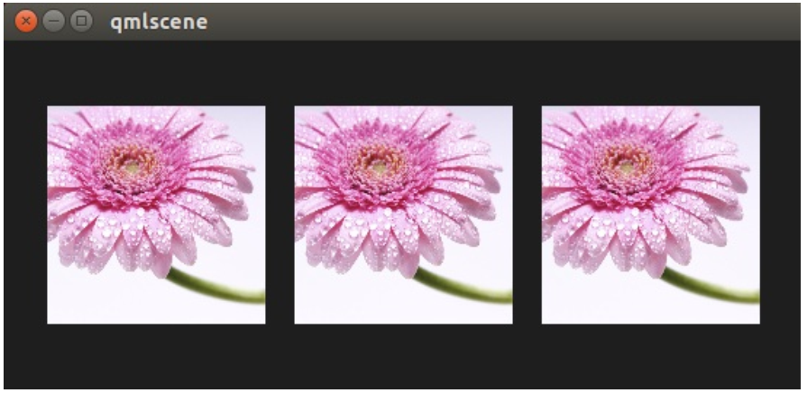
默认下着色器使用这个资源并且不作任何改变进行渲染。示例代码:defaultshader.qml
import QtQuick 2.0
Rectangle {
    width: 480; height: 240
    color: '#1e1e1e'

    Row {
        anchors.centerIn: parent
        spacing: 20
        Image {
            id: sourceImage
            width: 80; height: width
            source: 'assets/tulips.jpg'
        }
        ShaderEffect {
            id: effect
            width: 80; height: width
            property variant source: sourceImage
        }
        ShaderEffect {
            id: effect2
            width: 80; height: width
            // the source where the effect shall be applied to
            property variant source: sourceImage
            // default vertex shader code
            vertexShader: "
                uniform highp mat4 qt_Matrix;
                attribute highp vec4 qt_Vertex;
                attribute highp vec2 qt_MultiTexCoord0;
                varying highp vec2 qt_TexCoord0;
                void main() {
                    qt_TexCoord0 = qt_MultiTexCoord0;
                    gl_Position = qt_Matrix * qt_Vertex;
                }"
            // default fragment shader code
            fragmentShader: "
                varying highp vec2 qt_TexCoord0;
                uniform sampler2D source;
                uniform lowp float qt_Opacity;
                void main() {
                    gl_FragColor = texture2D(source, qt_TexCoord0) * qt_Opacity;
                }"
        }
    }
}
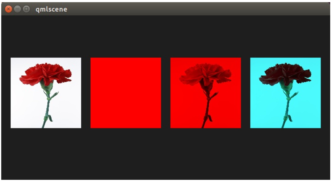
在上边这个例子中,我们在一行中显示了 3 张图片,第一张是原始图片,第二张使用默认的着色器渲染出来的图片,第三张使用了 Qt5 源码中默认的顶点与片段着色器的代码进行渲染的图片。
让我们仔细看看着色器代码。
vertexShader: "
    uniform highp mat4 qt_Matrix;
    attribute highp vec4 qt_Vertex;
    attribute highp vec2 qt_MultiTexCoord0;
    varying highp vec2 qt_TexCoord0;
    void main() {
        qt_TexCoord0 = qt_MultiTexCoord0;
        gl_Position = qt_Matrix * qt_Vertex;
    }"
着色器代码来自 Qt 这边的一个字符串,绑定了顶点着色器(vertexShader)与片段着色器(fragmentShader)属性。每个着色器代码必须有一个 main(){....}函数,它将被 GPU 执行。Qt 已经默认提供了以 qt_开头的变量。
下面是这些变量简短的介绍:
- uniform-在处理过程中不能够改变的值。
- attribute-连接外部数据
- varying-着色器之间的共享数据
- highp-高精度值
- lowp-低精度值
- mat4-4x4 浮点数(float)矩阵
- vec2-包含两个浮点数的向量
- sampler2D-2D 纹理
- float-浮点数
- 可以查看 openGL ES 2.0 API Quick Reference Card 获得更多信息。
现在我们可以更好的理解下面这些变量:
- qt_Matrix:model-view-projection(模型-视图-投影)矩阵
- qt_Vertex:当前顶点坐标
- qt_MultiTexCoord0:纹理坐标
- qt_TexCoord0:共享纹理坐标
我们已经有可以使用的投影矩阵(projection matrix),当前顶点与纹理坐标。纹理坐标与作为资源(source)的纹理相关。在 main()函数中,我们保存纹理坐标,留在后面的片段着色器中使用。每个顶点着色器都需要赋值给 gl_Postion,在这里使用项目矩阵乘以顶点,得到我们 3D 坐标系中的点。
片段着色器从顶点着色器中接收我们的纹理坐标,这个纹理仍然来自我们的 QML 资源属性(source property)。在着色器代码与 QML 之间传递变量是如此的简单。此外我们的透明值,在着色器中也可以使用,变量是 qt_Opacity。每个片段着色器需要给 gl_FragColor 变量赋值,在这里默认着色器代码使用资源纹理(source texture)的像素颜色与透明值相乘。
fragmentShader: "
    varying highp vec2 qt_TexCoord0;
    uniform sampler2D source;
    uniform lowp float qt_Opacity;
    void main() {
        gl_FragColor = texture2D(source, qt_TexCoord0) * qt_Opacity;
    }"
在后面的例子中,我们将会展示一些简单的着色器例子。首先我们会集中在片段着色器上,然后在回到顶点着色器上。
¶ 5. 片段着色器(Fragement Shader)
片段着色器调用每个需要渲染的像素。我们将开发一个红色透镜,它将会增加图片的红色通道的值。
¶ 5.1 配置场景(Setting up the scene)
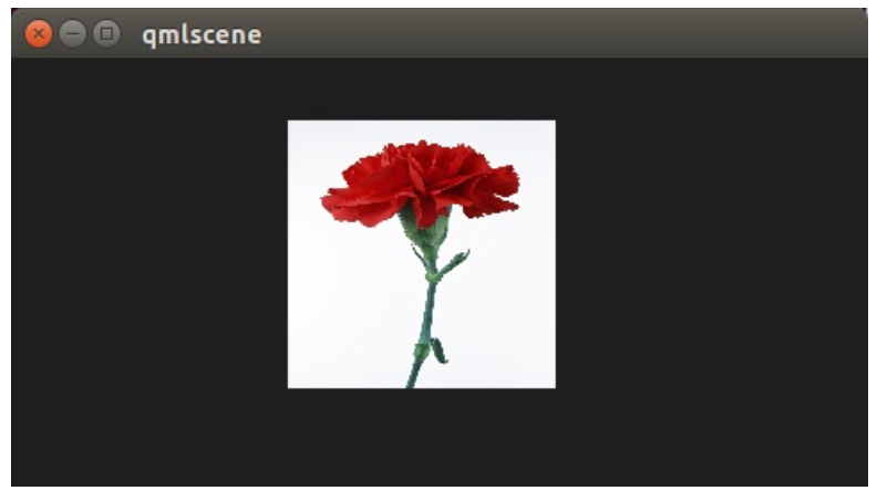
首先我们配置我们的场景,在区域中央使用一个网格显示我们的源图片(source image)。示例代码:redlense1.qml
import QtQuick 2.0
Rectangle {
    width: 480; height: 240
    color: '#1e1e1e'
    Grid {
        anchors.centerIn: parent
        spacing: 20
        rows: 2; columns: 4
        Image {
            id: sourceImage
            width: 150; height: width
            source: 'assets/tulips.jpg'
        }
    }
}
¶ 5.2 红色着色器(A red Shader)
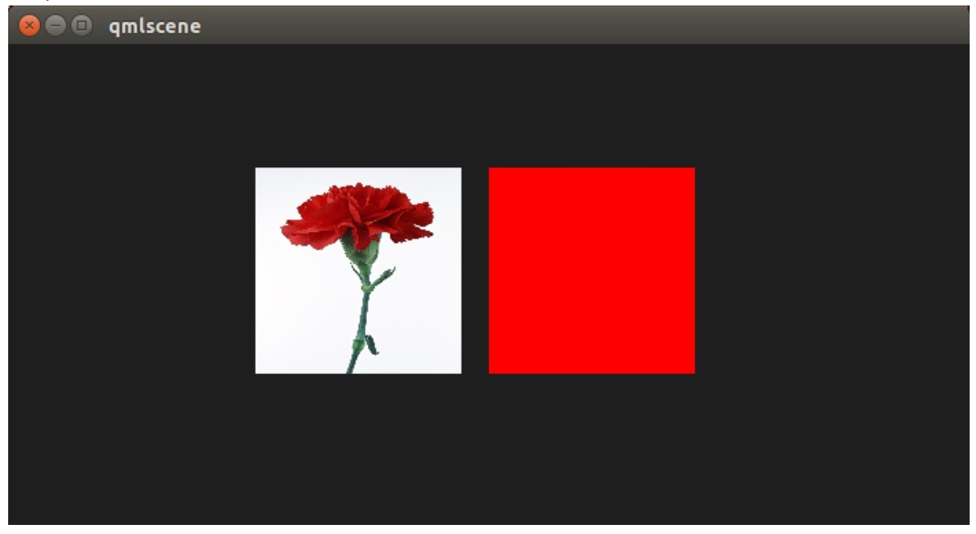
下一步我们添加一个着色器,显示一个红色矩形框。由于我们不需要纹理,我们从顶点着色器中移除纹理。示例代码:redlense2.qml
vertexShader: "
    uniform highp mat4 qt_Matrix;
    attribute highp vec4 qt_Vertex;
    void main() {
        gl_Position = qt_Matrix * qt_Vertex;
    }"
    fragmentShader: "
        uniform lowp float qt_Opacity;
        void main() {
            gl_FragColor = vec4(1.0, 0.0, 0.0, 1.0) * qt_Opacity;
        }"
在片段着色器中,我们简单的给 gl_FragColor 赋值为 vec4(1.0, 0.0, 0.0, 1.0),它代表红色,并且不透明(alpha=1.0)。
使用纹理的红色着色器(A red shader with texture)
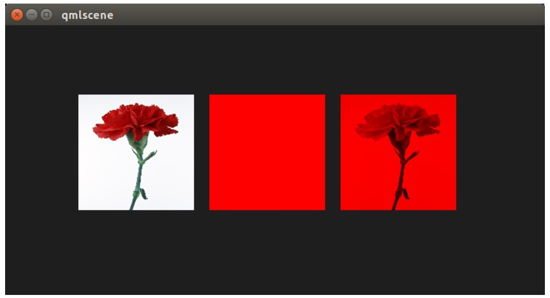
现在我们想要将这个红色应用在纹理的每个像素上。我们需要将纹理加回顶点着色器。由于我们不再在顶点着色器中做任何其它的事情,所以默认的顶点着色器已经满足我们的要求。
ShaderEffect {
    id: effect2
    width: 80; height: width
    property variant source: sourceImage
    visible: root.step>1
    fragmentShader: "
    varying highp vec2 qt_TexCoord0;
    uniform sampler2D source;
    uniform lowp float qt_Opacity;
    void main() {
        gl_FragColor = texture2D(source, qt_TexCoord0) * vec4(1.0, 0.0, 0.0, 1.0) * qt_Opacity;
    }"
}
完整的着色器重新包含我们的源图片作为属性,由于我们没有特殊指定,使用默认的顶点着色器,我没有重写顶点着色器。在片段着色器中,我们提取纹理片段 texture2D(source,qt_TexCoord0),并且与红色一起应用。
¶ 5.3 红色通道属性(The red channel property)
这样的代码用来修改红色通道的值看起来不是很好,所以我们想要将这个值包含在 QML 这边。我们在 ShaderEffect 中增加一个 redChannel 属性,并在我们的片段着色器中申明一个 uniform lowpfloat redChannel。这就是从一个着色器代码中标记一个值到 QML 这边的方法,非常简单。
ShaderEffect {
    id: effect3
    width: 80; height: width
    property variant source: sourceImage
    property real redChannel: 0.3
    visible: root.step>2
    fragmentShader: "
    varying highp vec2 qt_TexCoord0;
    uniform sampler2D source;
    uniform lowp float qt_Opacity;
    uniform lowp float redChannel;
    void main() {
        gl_FragColor = texture2D(source, qt_TexCoord0) * vec4(redChannel, 1.0, 1.0, 1.0);
    }"
}
为了让这个透镜更真实,我们改变 vec4 颜色为 vec4(redChannel, 1.0, 1.0, 1.0),这样其它颜色与 1.0 相乘,只有红色部分使用我们的 redChannel 变量。
¶ 5.4 红色通道的动画(The red channel animated)
由于 redChannel 属性仅仅是一个正常的属性,我们也可以像其它 QML 中的属性一样使用动画。我们使用 QML 属性在 GPU 上改变这个值,来影响我们的着色器,这真酷!
ShaderEffect {
    id: effect4
    width: 80; height: width
    property variant source: sourceImage
    property real redChannel: 0.3
    visible: root.step>3
    NumberAnimation on redChannel {
    from: 0.0; to: 1.0; loops: Animation.Infinite; duration: 4000
    }
    fragmentShader: "
        varying highp vec2 qt_TexCoord0;
        uniform sampler2D source;
        uniform lowp float qt_Opacity;
        uniform lowp float redChannel;
        void main() {
            gl_FragColor = texture2D(source, qt_TexCoord0) * vec4(redChannel, 1.0, 1.0, 1.0);
    }"
}
下面是最后的结果。
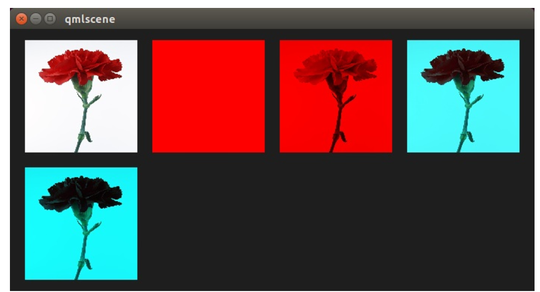
在这 4 秒内,第二排的着色器红色通道的值从 0.0 到 1.0。 图片从没有红色信息(0.0 red)到一个正常的图片(1.0 red)。
¶ 6. 波浪效果(Wave Effect)
在这个更加复杂的例子中,我们使用片段着色器创建一个波浪效果。波浪的形成是基于 sin 曲线,并且它影响了使用的纹理坐标的颜色。示例代码:wave.qml
import QtQuick 2.0

Rectangle {
    width: 480; height: 240
    color: '#1e1e1e'
    Row {
        anchors.centerIn: parent
        spacing: 20
        Image {
            id: sourceImage
            width: 160; height: width
            source: "assets/coastline.jpg"
        }
        ShaderEffect {
            width: 160; height: width
            property variant source: sourceImage
            property real frequency: 8
            property real amplitude: 0.1
            property real time: 0.0
            NumberAnimation on time {
                from: 0; to: Math.PI*2; duration: 1000; loops: Animation.Infinite
            }
            fragmentShader: "
                varying highp vec2 qt_TexCoord0;
                uniform sampler2D source;
                uniform lowp float qt_Opacity;
                uniform highp float frequency;
                uniform highp float amplitude;
                uniform highp float time;
                void main() {
                    highp vec2 pulse = sin(time - frequency * qt_TexCoord0);
                    highp vec2 coord = qt_TexCoord0 + amplitude * vec2(pulse.x, -pulse.x);
                    gl_FragColor = texture2D(source, coord) * qt_Opacity;
                }"
        }
    }
}
波浪的计算是基于一个脉冲与纹理坐标的操作。我们使用一个基于当前时间与使用的纹理坐标的 sin 波浪方程式来实现脉冲。
highp vec2 pulse = sin(time - frequency * qt_TexCoord0);
离开了时间的因素,我们仅仅只有扭曲,而不是像波浪一样运动的扭曲。
我们使用不同的纹理坐标作为颜色。
highp vec2 coord = qt_TexCoord0 + amplitude * vec2(pulse.x, -pulse.x);
纹理坐标受我们的 x 脉冲值影响,结果就像一个移动的波浪。
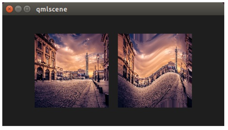
如果我们没有在片段着色器中使用像素的移动,这个效果可以首先考虑使用顶点着色器来完成。
¶ 7. 顶点着色器(Vertex Shader)
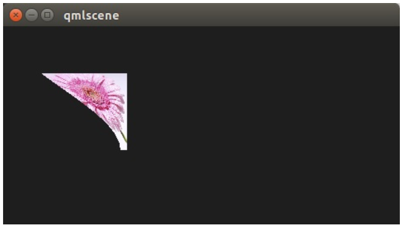
顶点着色器用来操作 ShaderEffect 提供的顶点。正常情况下,ShaderEffect 有 4 个顶点(左上 top-left,右上 top-right,左下 bottom-left,右下 bottom-right)。每个顶点使用 vec4 类型记录。为了实现顶点着色器的可视化,我们将编写一个吸收的效果。这个效果通常被用来让一个矩形窗口消失为一个点。
¶ 7.1 配置场景(Setting up the scene)
首先我们再一次配置场景。实例代码:genie.qml
import QtQuick 2.0

Rectangle {
    width: 480; height: 240
    color: '#1e1e1e'

    Image {
        id: sourceImage
        width: 160; height: width
        source: "assets/lighthouse.jpg"
        visible: false
    }
    Rectangle {
        width: 160; height: width
        anchors.centerIn: parent
        color: '#333333'
    }
    ShaderEffect {
        id: genieEffect
        width: 160; height: width
        anchors.centerIn: parent
        property variant source: sourceImage
        property bool minimized: false
        MouseArea {
            anchors.fill: parent
            onClicked: genieEffect.minimized = !genieEffect.minimized
        }
    }
}
这个场景使用了一个黑色背景,并且提供了一个使用图片作为资源纹理的 ShaderEffect。 使用 image 元素的原图片是不可见的,只是给我们的吸收效果提供资源。此外我们在 ShaderEffect 的位置添加了一个同样大小的黑色矩形框,这样我们可以更加明确的知道我们需要点击哪里来重置效果。
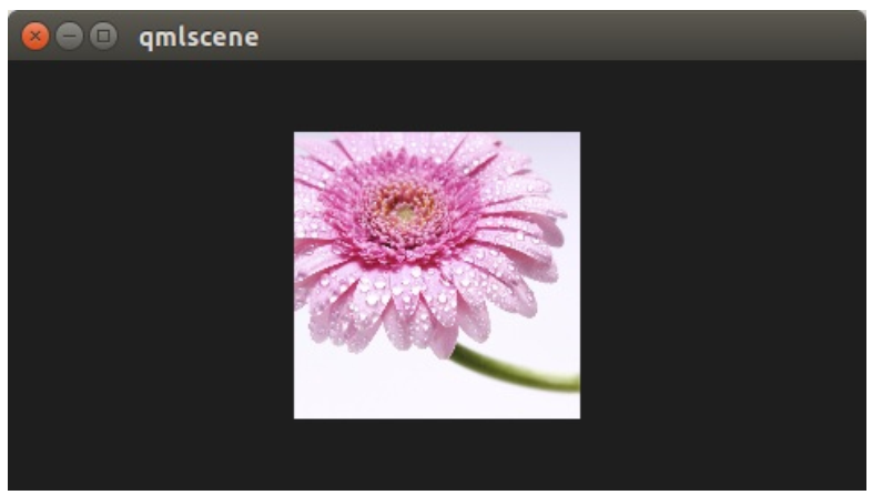
MouseArea 覆盖了 ShaderEffect。在 onClicked 操作中,我们绑定了自定义的布尔变量属性 minimized。我们稍后使用这个属性来触发效果。
¶ 7.2 最小化与正常化(Minimize and normalize)
在我们配置好场景后,我们定义一个 real 类型的属性,叫做 minimize,这个属性包含了我们当前最小化的值。这个值在 0.0 到 1.0 之间,由一个连续的动画来控制它。
property real minimize: 0.0
    SequentialAnimation on minimize {
        id: animMinimize
        running: genieEffect.minimized
        PauseAnimation { duration: 300 }
        NumberAnimation { to: 1; duration: 700; easing.type: Easing.InOutSine }
        PauseAnimation { duration: 1000 }
    }
    SequentialAnimation on minimize {
        id: animNormalize
        running: !genieEffect.minimized
        NumberAnimation { to: 0; duration: 700; easing.type: Easing.InOutSine }
        PauseAnimation { duration: 1300 }
    }
这个动画绑定了由 minimized 属性触发。现在我们已经配置好我们的环境,最后让我们看看顶点着色器的代码。
vertexShader: "
    uniform highp mat4 qt_Matrix;
    attribute highp vec4 qt_Vertex;
    attribute highp vec2 qt_MultiTexCoord0;
    varying highp vec2 qt_TexCoord0;
    uniform highp float minimize;
    uniform highp float width;
    uniform highp float height;
    void main() {
        qt_TexCoord0 = qt_MultiTexCoord0;
        highp vec4 pos = qt_Vertex;
        pos.y = mix(qt_Vertex.y, height, minimize);
        pos.x = mix(qt_Vertex.x, width, minimize);
        gl_Position = qt_Matrix * pos;
    }"
顶点着色器被每个顶点调用,在我们这个例子中,一共调用了四次。默认下提供 qt 已定义的参数,如 qt_Matrix,qt_Vertex,qt_MultiTexCoord0,qt_TexCoord0。 我们在之前已经讨论过这些变量。此外我们从 ShaderEffect 中链接 minimize,width 与 height 的值到我们的顶点着色器代码中。在 main 函数中,我们将当前纹理值保存在 qt_TexCoord()中,让它在片段着色器中可用。现在我们拷贝当前位置,并修改顶点的 x,y 的位置。
highp vec4 pos = qt_Vertex;
pos.y = mix(qt_Vertex.y, height, minimize);
pos.x = mix(qt_Vertex.x, width, minimize);
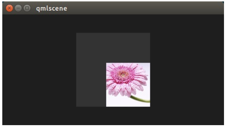
mix(...)函数提供了一种在两个参数之间(0.0 到 1.0)的线性插值的算法。在我们的例子中,在当前 y 值与高度值之间基于 minimize 的值插值获得 y 值,x 的值获取类似。记住 minimize 的值是由我们的连续动画控制,并且在 0.0 到 1.0 之间(反之亦然)。
¶ 7.3 基础弯曲(Primitive Bending)
我们已经完成了最小化我们的坐标。现在我们想要修改一下对 x 值的操作,让它依赖当前的 y 值。 这个改变很简单。 y 值计算在前。 x 值的插值基于当前顶点的 y 坐标。
highp float t = pos.y / height;
pos.x = mix(qt_Vertex.x, width, t * minimize);
这个结果造成当 y 值比较大时,x 的位置更靠近 width 的值。也就是说上面 2 个顶点根本不受影响,它们的 y 值始终为 0,下面两个顶点的 x 坐标值更靠近 width 的值,它们最后转向同一个 x 值。
import QtQuick 2.0

Rectangle {
    width: 480; height: 240
    color: '#1e1e1e'
    Image {
        id: sourceImage
        width: 160; height: width
        source: "assets/lighthouse.jpg"
        visible: false
    }
    Rectangle {
        width: 160; height: width
        anchors.centerIn: parent
        color: '#333333'
    }
    ShaderEffect {
        id: genieEffect
        width: 160; height: width
        anchors.centerIn: parent
        property variant source: sourceImage
        property real minimize: 0.0
        property bool minimized: false

        SequentialAnimation on minimize {
            id: animMinimize
            running: genieEffect.minimized
            PauseAnimation { duration: 300 }
            NumberAnimation { to: 1; duration: 700; easing.type: Easing.InOutSine }
            PauseAnimation { duration: 1000 }
        }
        SequentialAnimation on minimize {
            id: animNormalize
            running: !genieEffect.minimized
            NumberAnimation { to: 0; duration: 700; easing.type: Easing.InOutSine }
            PauseAnimation { duration: 1300 }
        }
        vertexShader: "
            uniform highp mat4 qt_Matrix;
            uniform highp float minimize;
            uniform highp float height;
            uniform highp float width;
            attribute highp vec4 qt_Vertex;
            attribute highp vec2 qt_MultiTexCoord0;
            varying highp vec2 qt_TexCoord0;
            void main() {
                qt_TexCoord0 = qt_MultiTexCoord0;
                // M1>>
                highp vec4 pos = qt_Vertex;
                pos.y = mix(qt_Vertex.y, height, minimize);
                highp float t = pos.y / height;
                pos.x = mix(qt_Vertex.x, width, t * minimize);
                gl_Position = qt_Matrix * pos;
现在简单的弯曲并不能真正的满足我们的要求,我们将添加几个部件来提升它的效果。 首先我们增加动画,支持一个自定义的弯曲属性。这是非常必要的,由于弯曲立即发生,y 值的最小化需要被推迟。两个动画在同一持续时间计算总和(300+700+100 与 700+1300)。
property real bend: 0.0
property bool minimized: false

// change to parallel animation
ParallelAnimation {
    id: animMinimize
    running: genieEffect.minimized
    SequentialAnimation {
        PauseAnimation { duration: 300 }
        NumberAnimation {
            target: genieEffect; property: 'minimize';
            to: 1; duration: 700;
            easing.type: Easing.InOutSine
        }
        PauseAnimation { duration: 1000 }
    }
    // adding bend animation
    SequentialAnimation {
        NumberAnimation {
            target: genieEffect; property: 'bend'
            to: 1; duration: 700;
            easing.type: Easing.InOutSine }
        PauseAnimation { duration: 1300 }
    }
}
此外,为了使弯曲更加平滑,不再使用 y 值影响 x 值的弯曲函数,pos.x 现在依赖新的弯曲属性动画:
highp float t = pos.y / height;
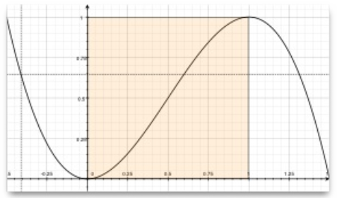
t = (3.0 - 2.0 * t) * t * t;
pos.x = mix(qt_Vertex.x, width, t * bend);
弯曲从 0.0 平滑开始,逐渐加快,在 1.0 时逐渐平滑。下面是这个函数在指定范围内的曲线图。 对于我们,只需要关注 0 到 1 的区间。
想要获得最大化的视觉改变,需要增加我们的顶点数量。可以使用网眼(mesh)来增加顶点:
mesh: GridMesh { resolution: Qt.size(16, 16) }
现在 ShaderEffect 被分布为 16x16 顶点的网格,替换了之前 2x2 的顶点。这样顶点之间的插值将会看起来更加平滑。
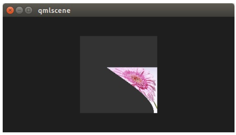
你可以看见曲线的变化,在最后让弯曲变得非常平滑。这让弯曲有了更加强大的效果。
¶ 7.4 侧面收缩(Choosing Sides)
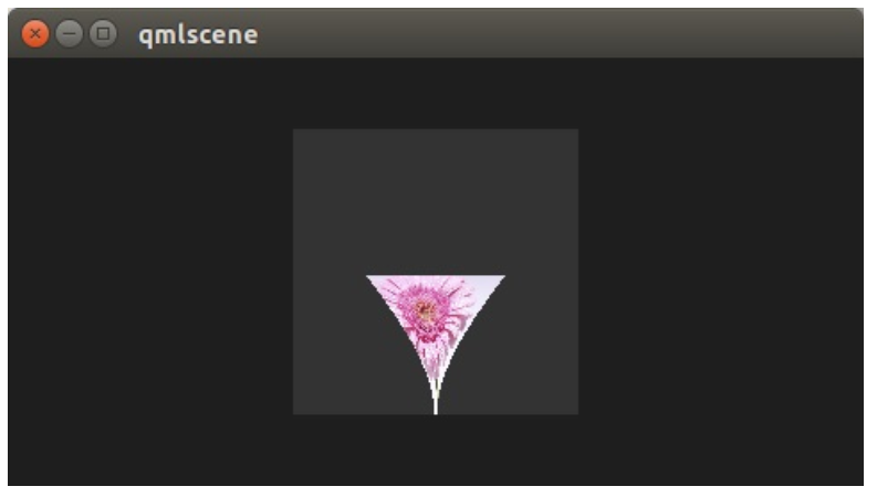
最后一个增强,我们希望能够收缩边界。边界朝着吸收的点消失。直到现在它总是在朝着 width 值的点消失。添加一个边界属性,我们能够修改这个点在 0 到 width 之间。
ShaderEffect {
    ...
    property real side: 0.5
    vertexShader: "
        ...
        uniform highp float side;
        ...
        pos.x = mix(qt_Vertex.x, side * width, t * bend);
    "
}
¶ 7.5 包装(Packing)
最后将我们的效果包装起来。将我们吸收效果的代码提取到一个叫做 GenieEffect 的自定义组件中。它使用 ShaderEffect 作为根元素。移除掉 MouseArea,这不应该放在组件中。绑定 minimized 属性来触发效果。
import QtQuick 2.0

ShaderEffect {
    id: genieEffect
    width: 160; height: width
    anchors.centerIn: parent
    property variant source
    mesh: GridMesh { resolution: Qt.size(10, 10) }
    property real minimize: 0.0
    property real bend: 0.0
    property bool minimized: false
    property real side: 1.0

    ParallelAnimation {
        id: animMinimize
        running: genieEffect.minimized
        SequentialAnimation {
            PauseAnimation { duration: 300 }
            NumberAnimation {
                target: genieEffect; property: 'minimize';
                to: 1; duration: 700;
                easing.type: Easing.InOutSine
            }
            PauseAnimation { duration: 1000 }
        }
        SequentialAnimation {
            NumberAnimation {
                target: genieEffect; property: 'bend'
                to: 1; duration: 700;
                easing.type: Easing.InOutSine }
            PauseAnimation { duration: 1300 }
        }
    }
    ParallelAnimation {
        id: animNormalize
        running: !genieEffect.minimized
        SequentialAnimation {
            NumberAnimation {
                target: genieEffect; property: 'minimize';
                to: 0; duration: 700;
                easing.type: Easing.InOutSine
            }
            PauseAnimation { duration: 1300 }
        }
        SequentialAnimation {
            PauseAnimation { duration: 300 }
            NumberAnimation {
                target: genieEffect; property: 'bend'
                to: 0; duration: 700;
                easing.type: Easing.InOutSine }
            PauseAnimation { duration: 1000 }
        }
    }
    vertexShader: "
        uniform highp mat4 qt_Matrix;
        attribute highp vec4 qt_Vertex;
        attribute highp vec2 qt_MultiTexCoord0;
        uniform highp float height;
        uniform highp float width;
        uniform highp float minimize;
        uniform highp float bend;
        uniform highp float side;
        varying highp vec2 qt_TexCoord0;
        void main() {
            qt_TexCoord0 = qt_MultiTexCoord0;
            highp vec4 pos = qt_Vertex;
            pos.y = mix(qt_Vertex.y, height, minimize);
            highp float t = pos.y / height;
            t = (3.0 - 2.0 * t) * t * t;
            pos.x = mix(qt_Vertex.x, side * width, t * bend);
            gl_Position = qt_Matrix * pos;
        }"
}
你现在可以像这样简单的使用这个效果:
import QtQuick 2.0

Rectangle {
    width: 480; height: 240
    color: '#1e1e1e'
    GenieEffect {
        source: Image { source: 'assets/lighthouse.jpg' }
        MouseArea {
            anchors.fill: parent
            onClicked: parent.minimized = !parent.minimized
        }
    }
}
我们简化了代码,移除了背景矩形框,直接使用图片完成效果,替换了在一个单独的图像元素中加载它。
¶ 8. 屏幕效果(Curtain Effect)
在的自定义效果例子中,我们将带来一个剧幕效果。
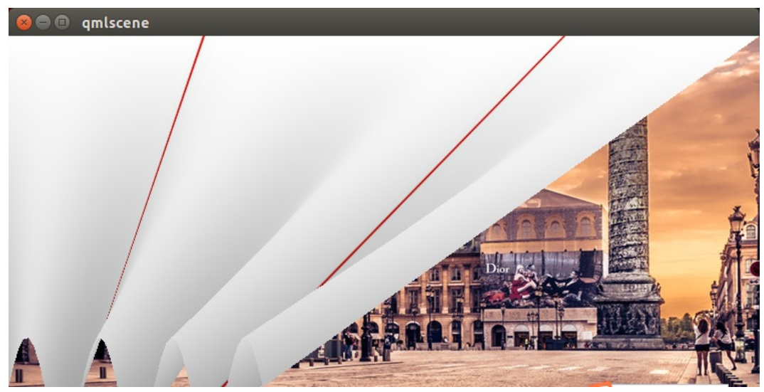
只有一个小组件作为背景,剧幕实际上是一张图片,它是 ShaderEffect 的资源。整个效果使用顶点着色器来摆动剧幕,使用片段着色器提供阴影的效果。下面是一个简单的图片,让你更加容易理解代码。
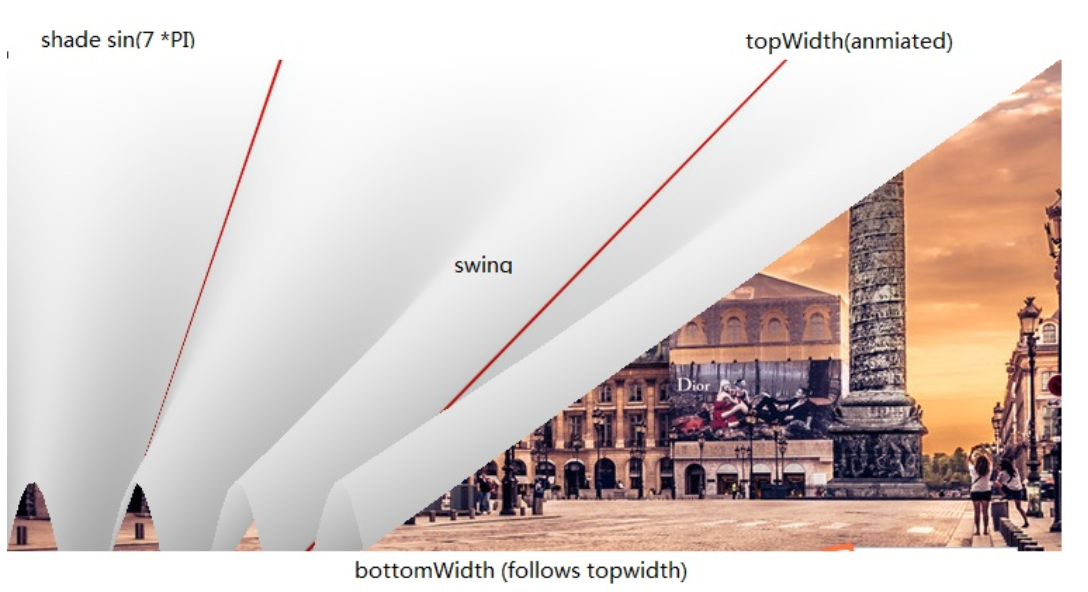
剧幕的波形阴影通过一个在剧幕宽度上的 sin 曲线使用 7 的振幅来计算(7*PI=221.99..)另一个重要的部分是摆动,当剧幕打开或者关闭时,使用动画来播放剧幕的 topWidth。bottomWidth 使用 SpringAnimation 来跟随 topWidth 变化。这样我们就能创建出底部摆动的剧幕效果。计算得到的 swing 提供了摇摆的强度,用来对顶点的 y 值进行插值。
在阴影的使用上没有新的东西加入,唯一不同的是在顶点着色器中操作 gl_Postion 和片段着色器中操作 gl_FragColor。
实例代码:CurtainEffect.qml
import QtQuick 2.0

ShaderEffect {
    anchors.fill: parent

    mesh: GridMesh {
        resolution: Qt.size(50, 50)
    }
    property real topWidth: open?width:20
    property real bottomWidth: topWidth
    property real amplitude: 0.1
    property bool open: false
    property variant source: effectSource

    Behavior on bottomWidth {
        SpringAnimation {
            easing.type: Easing.OutElastic;
            velocity: 250; mass: 1.5;
            spring: 0.5; damping: 0.05
        }
    }
    Behavior on topWidth {
        NumberAnimation { duration: 1000 }
    }

    ShaderEffectSource {
        id: effectSource
        sourceItem: effectImage;
        hideSource: true
    }
    Image {
        id: effectImage
        anchors.fill: parent
        source: "assets/fabric.jpg"
        fillMode: Image.Tile
    }
    vertexShader: "
        attribute highp vec4 qt_Vertex;
        attribute highp vec2 qt_MultiTexCoord0;
        uniform highp mat4 qt_Matrix;
        varying highp vec2 qt_TexCoord0;
        varying lowp float shade;
        uniform highp float topWidth;
        uniform highp float bottomWidth;
        uniform highp float width;
        uniform highp float height;
        uniform highp float amplitude;
        void main() {
            qt_TexCoord0 = qt_MultiTexCoord0;
            highp vec4 shift = vec4(0.0, 0.0, 0.0, 0.0);
            highp float swing = (topWidth - bottomWidth) * (qt_Vertex.y / height);
            shift.x = qt_Vertex.x * (width - topWidth + swing) / width;
            shade = sin(21.9911486 * qt_Vertex.x / width);
            shift.y = amplitude * (width - topWidth + swing) * shade;
            gl_Position = qt_Matrix * (qt_Vertex - shift);
            shade = 0.2 * (2.0 - shade ) * ((width - topWidth + swing) / width);
        }"
    fragmentShader: "
        uniform sampler2D source;
        varying highp vec2 qt_TexCoord0;
        varying lowp float shade;
        void main() {
            highp vec4 color = texture2D(source, qt_TexCoord0);
            color.rgb *= 1.0 - shade;
            gl_FragColor = color;
        }"
}
这个效果在 curtaindemo.qml 文件中使用。
import QtQuick 2.0

Rectangle {
    id: root
    width: 480; height: 240
    color: '#1e1e1e'

    Image {
        anchors.centerIn: parent
        source: 'assets/wiesn.jpg'
    }
    CurtainEffect {
        id: curtain
        anchors.fill: parent
    }
    MouseArea {
        anchors.fill: parent
        onClicked: curtain.open = !curtain.open
    }
}
剧幕效果通过自定义的 open 属性打开。我们使用了一个 MouseArea 来触发打开和关闭剧幕。
¶ 9. 圆角矩形效果(Squircle Effect)
本示例是展示 openGL 库如何应用在 qml 编写的界面中。下面将展示从 Qt 移植的示例效果。
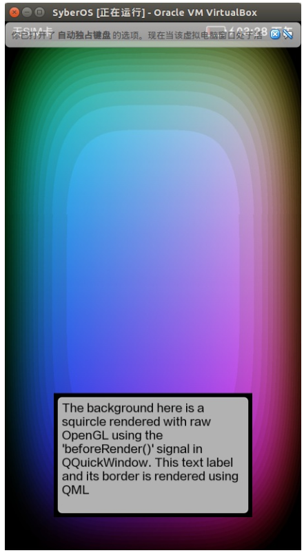
一个应用程序可以使用 qquickwindow::beforerendering() 信号,在 Qt Quick 的场景下的 openGL 绘制自定义内容。这个信号会在场景图开始绘制每一帧之前发射,因此作为这个信号响应任何 openGL 绘制调用,将 Qt Quick 元素堆栈的下面。
作为一种替代方法,应用程序想要渲染的 openGL 内容上的 Qt Quick 的场景,可以通过连接到 qquickwindow::afterrendering()信号。
在这个例子中,我们也将看到它是如何可能已经暴露在 QML 影响 openGL 绘制的值。 我们将使用一个 NumberAnimation 阈值在 QML 文件,该值由 openGL 着色器程序,得出 squircles 使用。
class Squircle : public QQuickItem
{
    Q_OBJECT
    Q_PROPERTY(qreal t READ t WRITE setT NOTIFY tChanged)
public:
    Squircle();
    qreal t() const { return m_t; }
    void setT(qreal t);
signals:
    void tChanged();
public slots:
    void sync();
    void cleanup();
private slots:
    void handleWindowChanged(QQuickWindow *win);
private:
    qreal m_t;
    SquircleRenderer *m_renderer;
};
首先,我们需要暴露在 QML 对象。这是 QQuickItem 的子类,所以我们可以很容易的访问 QQuickItem::window() 。
class SquircleRenderer : public QObject {
    Q_OBJECT
public:
    SquircleRenderer() : m_t(0), m_program(0) { }
    ~SquircleRenderer();
    void setT(qreal t) { m_t = t; }
    void setViewportSize(const QSize &size) { m_viewportSize = size; }
public slots:
    void paint();
we want to connect to QQuickWindow::beforeRendering()
private:
    QSize m_viewportSize;
    qreal m_t;
    QOpenGLShaderProgram *m_program;
};
然后我们需要一个对象来渲染。这种情况需要分开 QQuickItem,因为元素的生命周期在 GUI 线程中和渲染可能发生在渲染线程。因为我们要连接 QQuickWindow::beforerendering() 渲染一个对象。渲染器包含一份拷贝对象的声明在独立的 GUI 线程。
注意:不要试图将两者合并成一个对象。QQuickItems 可以在 GUI 线程删除渲染线程渲染。
让我们继续执行。
Squircle::Squircle()
    : m_t(0)
    , m_renderer(0)
{
    connect(this, SIGNAL(windowChanged(QQuickWindow*)), this, SLOT(handleWindowChanged(QQuickWindow*)
}
Squircle 类的构造函数初始化变量,并连接到窗口信号,当信号变化将使用我们渲染器。
void Squircle::handleWindowChanged(QQuickWindow *win)
{
    if (win) {
        connect(win, SIGNAL(beforeSynchronizing()), this, SLOT(sync()), Qt::DirectConnection);
        connect(win, SIGNAL(sceneGraphInvalidated()), this, SLOT(cleanup()), Qt::DirectConnection);
一旦我们有一个窗口,我们依赖于 QQuickWindow::beforeSynchronizing()信号,创建渲染和复制状态为安全。我们也连接到 QQuickWindow::sceneGraphInvalidated() 信号处理的渲染器的清理。
注:由于 Squircle 对象有 GUI 线程和从渲染线程发出的信号,它的连接是用 Qt::DirectConnection 。如果不这样做,会导致槽上不存在错误的线程中调用 openGL 上下文。
        win->setClearBeforeRendering(false);
    }
}
场景图的默认行为是在渲染之前清除帧。这意味着我们需要明确自己的 paint()功能。
void Squircle::sync()
{
    if (!m_renderer) {
        m_renderer = new SquircleRenderer();
        connect(window(), SIGNAL(beforeRendering()), m_renderer, SLOT(paint()), Qt::DirectConnection)
    }
    m_renderer->setViewportSize(window()->size() * window()->devicePixelRatio());
    m_renderer->setT(m_t);
}
我们利用 sync()函数初始化渲染和复制状态在我们的项目渲染器。当渲染对象被创造,我们也将 QQuickWindow::beforeRendering() 到渲染对象 paint()槽。
注: QQuickWindow::beforeSynchronizing()信号是在渲染线程在 GUI 线程发出的,所以它是安全的简单复制的值没有任何额外的保护。
void Squircle::cleanup()
{
    if (m_renderer) {
        delete m_renderer;
        m_renderer = 0;
    }
}
SquircleRenderer::~SquircleRenderer()
{
    delete m_program;
}
在 cleanup() 函数中,我们删除渲染对象并依次清理好自己的资源。
void Squircle::setT(qreal t)
{
    if (t == m_t)
        return;
        m_t = t;
        emit tChanged();
        if (window())
        window()->update();
}
当 t 值的变化,我们调用 QQuickWindow::update()相当与调用 QQuickItem::update() 因为前者会迫使整个窗口被重画,即使场景图没有自上一帧的改变。
void SquircleRenderer::paint()
{
    if (!m_program) {
        m_program = new QOpenGLShaderProgram();
        m_program->addShaderFromSourceCode(QOpenGLShader::Vertex,
                                        "attribute highp vec4 vertices;"
                                        "varying highp vec2 coords;"
                                        "void main() {"
                                        " gl_Position = vertices;"
                                        " coords = vertices.xy;"
                                        "}");
        m_program->addShaderFromSourceCode(QOpenGLShader::Fragment,
                                        "uniform lowp float t;"
                                        "varying highp vec2 coords;"
                                        "void main() {"
                                        " lowp float i = 1. - (pow(abs(coords.x), 4.) + pow(abs(coords.y), 4.));"
                                        " i = smoothstep(t - 0.8, t + 0.8, i);"
                                        " i = floor(i * 20.) / 20.;"
                                        " gl_FragColor = vec4(coords * .5 + .5, i, i);"
                                        "}");
        m_program->bindAttributeLocation("vertices", 0);
        m_program->link();
}
在 SquircleRenderer::paint() 函数首先初始化着色器程序。通过初始化着色器程序这里,我们确保 openGL 上下文绑定是在正确的线程。
m_program->bind();
    m_program->enableAttributeArray(0);
    float values[] = {
        -1, -1,
        1, -1,
        -1, 1,
        1, 1
    };
    m_program->setAttributeArray(0, GL_FLOAT, values, 2);
    m_program->setUniformValue("t", (float) m_t);
    glViewport(0, 0, m_viewportSize.width(), m_viewportSize.height());
    glDisable(GL_DEPTH_TEST);
    glClearColor(0, 0, 0, 1);
    glClear(GL_COLOR_BUFFER_BIT);
    glEnable(GL_BLEND);
    glBlendFunc(GL_SRC_ALPHA, GL_ONE);
    glDrawArrays(GL_TRIANGLE_STRIP, 0, 4);
    m_program->disableAttributeArray(0);
    m_program->release();
}
我们使用的着色器程序绘制 squircle。在 paint 结束我们释放和禁用属性,我们使用 openGL 上下文是一个干净的状态。
在 main 函数中向 QML 中注册 Squircle 类型。
qmlRegisterType<Squircle>("OpenGLUnderQML", 1, 0, "Squircle");
我们实例化 Squircle 变量,并用 T 的值创建一个数值动画。
import QtQuick 2.0
import OpenGLUnderQML 1.0

Item {
    width: 320
    height: 480
    Squircle {
        SequentialAnimation on t {
            NumberAnimation { to: 1; duration: 2500; easing.type: Easing.InQuad }
            NumberAnimation { to: 0; duration: 2500; easing.type: Easing.OutQuad }
            loops: Animation.Infinite
            running: true
        }
}
然后,我们一段文本覆盖它,事实上我们渲染 openGL 是在 Qt Quick 的下面。
Rectangle {
    color: Qt.rgba(1, 1, 1, 0.7)
    radius: 10
    border.width: 1
    border.color: "white"
    anchors.fill: label
    anchors.margins: -10
}
Text {
    id: label
    color: "black"
    wrapMode: Text.WordWrap
    text: "The background here is a squircle rendered with raw openGL using the 'beforeRender()'
    anchors.right: parent.right
    anchors.left: parent.left
    anchors.bottom: parent.bottom
    anchors.margins: 20
    }
}